
Beautiful Plants For Your Interior
Beautiful Plants For Your Interior

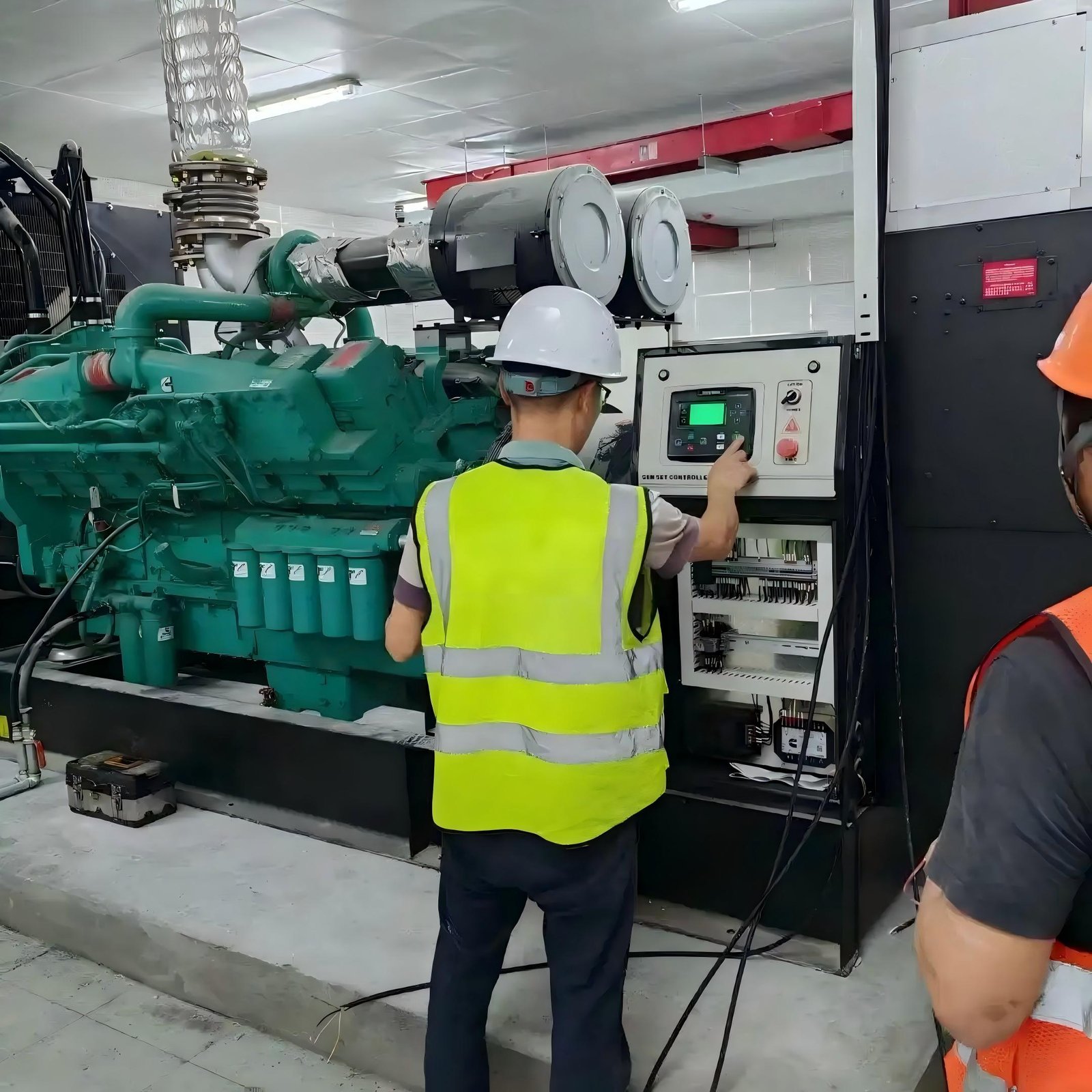
Start-up Preparation → Starting the Diesel Engine → Idle Warm-up → Speed Increase and Voltage Stabilization → Grid Connection/Independent Load Output of Electrical Energy → Steady-State Operation.
1. Check fuel, engine oil, and coolant levels; bleed the fuel lines.
2. Turn on the starter power; the control system performs a self-check: battery voltage, water temperature and oil pressure sensors, speed sensor, voltage transformer, and protection modules are normal.
3. Open the no-load switch (no load connected); power on the governor and AVR automatic voltage regulator for standby.
4. For manual units: press the pre-fuel pump to establish engine oil pressure; for automated units, automatic pre-lubrication is performed.
1. The control system outputs a signal to connect the starter motor (starter motor) power supply. The battery drives the starter motor to rotate the diesel engine crankshaft.
2. The crankshaft drives the camshaft to rotate, and the high-pressure fuel pump starts pumping fuel. Diesel fuel is sent to the injectors through the high-pressure fuel line.
3. The piston compresses the air in the cylinder. The temperature at the end of compression is 500~700℃, reaching the auto-ignition point of diesel fuel.
4. The injector atomizes the diesel fuel under high pressure and injects it into the high-temperature cylinder. The diesel fuel ignites under compression (diesel vehicles do not have spark plugs; this is compression ignition rather than spark ignition, commonly known in the industry as “ignition starting”).
5. The cylinder explodes and performs power. The diesel engine runs on its own combustion power. The starter motor is released, and the starter motor disengages from the flywheel.
At this time, the diesel engine is at low starting speed, and the fuel pressure and water temperature have not yet reached the required levels.
1. The governor controls the fuel injection quantity to maintain a low idle speed (usually 600~800 rpm);
2. The oil pressure gradually rises to the rated oil pressure, the coolant heats up, and the engine parts are heated evenly to avoid cold-start wear;
3. The generator rotates synchronously with the crankshaft at low speed: the generator excitation winding is provided with a weak excitation current by the AVR, and the stator induces a low residual voltage;
4. The control system monitors: if the oil pressure is too low, the water temperature is too high, or an overspeed fault occurs, the engine will immediately shut down for protection;
5. The warm-up time is 30 seconds to 3 minutes (extended for cold starts). After the oil pressure and water temperature stabilize and reach the standard, the speed can be increased.
1. The governor increases the fuel supply, and the diesel engine speed rises to the rated speed: – 50Hz power frequency unit: 1500r/min (4-pole generator, mainstream in China) – 60Hz unit: 1800r/min
2. The generator rotor synchronously reaches the rated speed: the AVR automatically increases the excitation current, and the rotor generates a strong magnetic field; the stator winding cuts the magnetic lines of force, and the induced voltage rises rapidly;
3. The voltage rises to the rated value (commonly three-phase 400V/single-phase 230V), and the AVR finely adjusts the excitation current in real time to stabilize the output voltage;
The control system collects voltage and frequency signals, confirms that the voltage is stable at 380/400V and the frequency at 50Hz, and enters the ready state.
Two operating conditions: standby operation and grid-connected operation:
1. Standby Unit (Common in residential areas/factories):
1. Confirm voltage, frequency, and no alarms from any protection devices;
2. Manually/automatically close the output air switch (circuit breaker);
3. Three-phase AC power is transmitted to the load equipment via switches and cables, and the unit begins to output power;
4. Initially operate under light load, then gradually increase the load to avoid sudden increases in load causing speed and voltage drops.
Grid-connected Unit (Parallel with Mains Power): Synchronization conditions must be met: equal voltage, same frequency, consistent phase, and same phase sequence;
1. The synchronizing device adjusts the unit’s speed and voltage to match the mains parameters;
2. Close the grid-connected switch at the synchronization moment, and the unit shares power with the grid;
3. Distribute active/reactive power according to the set parameters.
1. Diesel Engine Side: Increased load → increased resistance → slight decrease in speed → the governor automatically increases fuel injection to restore 1500 r/min; decreased load reduces fuel supply to stabilize speed and frequency. The cooling and lubrication systems continuously circulate, and the temperature-controlled fan automatically starts and stops according to the water temperature.
2. Generator Electrical Side: Load fluctuations cause changes in output voltage. The AVR adjusts the excitation current in real time to ensure that the output voltage fluctuation is within ±5%.
3. Control System: Continuously monitors: oil pressure, water temperature, speed, voltage, current, power, overload, short circuit, leakage, etc. Immediate alarm or trip shutdown protection is activated upon the occurrence of abnormalities.